Wire Rod Shot Blasting — Dual-station Coil Batch System

Dual-station Coil Batch Shot Blasting System: one station may blast while the other is loaded or unloaded. This arrangement supports an alternating production rhythm; it is not continuous wire feed-through.

Complete the coil specification
Review fieldInformation to confirm
Coil geometryWire diameter, coil ID and OD, width and loaded mass including tooling.
Handling boundaryLifting, mandrel loading, unloading and transfer time outside the blast stage.
Process and acceptanceIncoming scale, required surface, downstream process and complete-cycle output target.
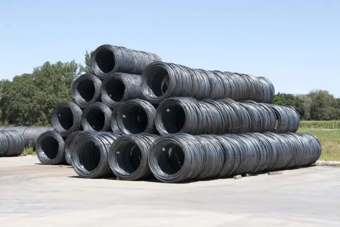
Coils of steel wire rod stacked outdoors
Wire-rod coils — workpiece reference; the supplied system is a coil-batch architecture, not continuous wire feed-through.

A Coil Batch Handling Architecture

Plan lifting, mandrel loading, blasting, unloading and downstream handling as distinct stages. Review coil geometry and support before defining the process.

Coil and Mandrel Limits

Loaded mass includes the coil and its fixtures or tooling. The per-mandrel limit is not a combined-system load rating. Coil width must be confirmed separately from mandrel working length.

Dual-station coil system

Wire diameter: Φ4.5–38 mm.

Minimum coil ID: 800 mm.

Maximum coil OD: 1500 mm.

Maximum load per mandrel: 2500 kg.

Loaded mass includes coil and fixtures or tooling; the load limit is per mandrel.

Conditional Process References

These references describe individual process settings. They do not establish a complete production cycle, coils per hour or tonnes per hour.

Dual-station coil system

Reference / conditional: Typical blast cycle: 7–15 min/coil.

Reference / conditional: Coil rotation: 10–20 rpm.

Reference / conditional: Reversal interval: 15 s.

Reference / conditional: Effective working length: 3800–5500 mm.

Blast/rotation/cleaning stage only; excludes external lifting/loading/unloading.

Mandrel/coil speed, not linear feed speed.

Adjustable dwell/reversal interval.

Customizable equipment/mandrel working length; not coil width.

Qualify the Full Production Requirement

Include external lifting, loading, unloading and transfer time when defining output. Provide coil width, geometry and surface condition for engineering review; do not infer these from working length or rotation speed.

Select the Wheel, Abrasive and Dust Package

Blast-wheel quantity and power, abrasive flow, total installed power and dust airflow must follow the confirmed coil and process configuration. No universal package is assumed.

Agree Cleaning and Downstream Acceptance

Specify the incoming scale condition, required cleanliness, surface profile and next process. Set inspection criteria for the actual wire and coil; a cleaning process is not automatically a validated peening process.

Lifecycle and Parts Identification

Keep the system identification, mandrel and selected wheel information available for maintenance and spare-parts enquiries. Support arrangements depend on the equipment and agreed scope.

Coil System Questions

Use coil-based inputs throughout the enquiry.

Is this continuous wire feed-through?

No. It is a dual-station coil batch system with alternating station duties.

Does blast time include crane handling?

No. The typical blast-stage reference excludes external lifting, loading and unloading.

Is working length the maximum coil width?

No. Mandrel working length and coil width are different fields; coil width requires confirmation.

Request Your Coil Machine Configuration

Send wire diameter, coil ID and OD, width, coil and tooling mass, lifting method, incoming scale, required finish and output target. Include drawings and the available floor plan.

Send us a message

Get a Quote

Get in Touch for Personalized Support and Solutions