
Steel Pipe Inner & Outer Shot Blasting Systems
Select external shot blasting and internal blasting as separate modules. They may be integrated in a project line after pipe geometry, handling and surface requirements are reviewed.
| Review field | Information to confirm |
|---|---|
| Geometry | Outside diameter, bore access, length, wall thickness and maximum mass. |
| Surface boundary | External, internal or both; incoming condition and accepted surface result for each. |
| Handling and output | Support, rotation or travel arrangement, loading and unloading, required output. |
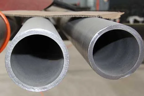
External, Internal or Combined
Identify which pipe surfaces require treatment before choosing the machine configuration.
External surface
Review pipe OD, support, rotation and travel through the external blasting module. External module specifications do not describe inner-wall performance.
Internal surface
Review internal access, pipe dimensions and the required surface condition for a separately selected internal module. Pressure, flow and speed must be defined for that module.
Combined project line
Coordinate the two modules, handling and inspection points as an agreed line scope. A standard external machine is not assumed to clean both surfaces.
External Module: Model and Pipe OD
These model-specific OD values support initial selection. HT140 maximum OD is stated separately; no minimum OD is specified here. Length, wall thickness and supported pipe mass require project confirmation.
HT10
Pipe OD range: Φ30–100 mm.
HT15
Pipe OD range: Φ50–150 mm.
HT20
Pipe OD range: Φ50–200 mm.
HT25
Pipe OD range: Φ50–250 mm.
HT30
Pipe OD range: Φ50–300 mm.
HT140
Maximum pipe OD: 1400 mm.
Minimum OD requires engineering confirmation.
Conditional External Module References
The following are external-module reference configurations. Final motor list, pressure loss and dust-system design determine project utilities. Abrasive flow is not pipe throughput, elevator capacity or separator capacity.
HT10
Reference / conditional: Abrasive flow rate: 2 × 250 kg/min.
Reference / conditional: Dust airflow: 5000 m³/h.
Reference / conditional: Total installed power: 50 kW.
External blasting module; two-wheel model reference, not inner-wall performance.
External module reference configuration; final project utilities per approved motor/dust-system design.
HT15
Reference / conditional: Abrasive flow rate: 2 × 250 kg/min.
Reference / conditional: Dust airflow: 5000 m³/h.
Reference / conditional: Total installed power: 50 kW.
External blasting module; two-wheel model reference, not inner-wall performance.
External module reference configuration; final project utilities per approved motor/dust-system design.
HT20
Reference / conditional: Abrasive flow rate: 2 × 250 kg/min.
Reference / conditional: Dust airflow: 5000 m³/h.
Reference / conditional: Total installed power: 50 kW.
External blasting module; two-wheel model reference, not inner-wall performance.
External module reference configuration; final project utilities per approved motor/dust-system design.
HT25
Reference / conditional: Abrasive flow rate: 2 × 250 kg/min.
Reference / conditional: Dust airflow: 6000 m³/h.
Reference / conditional: Total installed power: 50 kW.
External blasting module; two-wheel model reference, not inner-wall performance.
External module reference configuration; final project utilities per approved motor/dust-system design.
HT30
Reference / conditional: Dust airflow: 6000 m³/h.
Reference / conditional: Total installed power: 50 kW.
External module reference configuration; final project utilities per approved motor/dust-system design.
HT140
Reference / conditional: Dust airflow: 10000 m³/h.
Reference / conditional: Total installed power: 115 kW.
External module reference configuration; final project utilities per approved motor/dust-system design.
Keep the Capacity Fields Separate
Pipe travel and throughput depend on the workpiece and required finish. State pipe length, wall thickness, mass and output target separately. Confirm wheel quantity and power for the selected module; no universal wheel package is assumed. Specify abrasive flow in kg/min and elevator and separator rated capacities separately in t/h.
Plan Handling and Dust-system Interfaces
Review support spacing, loading and unloading, rotation, surface access and interfaces to the next process. Dust collection and utility requirements follow the selected module and project design. Define the required loading and transfer sequence, control interfaces and automation scope for engineering review; no standard automation package is assumed.
Agree Surface Acceptance Before Selection
Provide the current surface, required cleanliness and profile, and next process. Establish abrasive, process settings and inspection criteria for the actual pipe instead of assuming a universal cleaning result.
Service and Parts Planning
Record module identification and the selected wheel, wear-part and dust-system configuration for future service enquiries. Support is arranged within the agreed equipment and site scope.
Pipe Configuration Questions
Resolve the surface and handling boundary first.
Does an external machine clean the bore?
Internal blasting requires a separately selected module; combined treatment is a project integration decision.
Can a pipe production rate be read from abrasive flow?
No. Abrasive flow, pipe throughput, elevator rating and separator rating describe different quantities.
What is needed beyond pipe OD?
Provide length, wall thickness, maximum mass, current and required surface, handling method and output target.
Request Your Pipe Machine Configuration
Send pipe drawings, OD range, length, wall thickness, mass, target surfaces, output requirement, floor plan and utilities. Identify whether external, internal or combined treatment is required.
