Shot Blasting Machines Selected Around Your Workpiece

Start with the part you need to clean, how it can be handled and the surface required by the next process. Hitech supplies shot blasting equipment with configuration selected around those inputs.
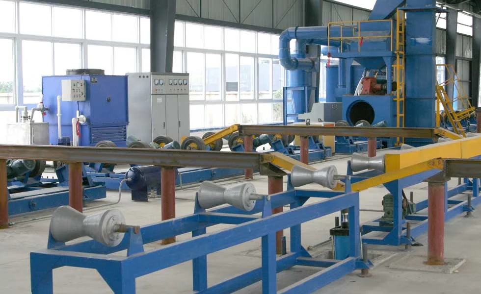
Pipe shot blasting line with roller supports and an enclosed treatment chamber
Pipe-handling equipment reference; the exact supplied modules and configuration are project-specific.
Small metal parts inside a perforated tumble blasting belt chamber
Tumble chamber reference — parts must tolerate contact and repeated turning.

Find the Machine Family That Fits the Workpiece

Compare handling architecture first. Detailed model limits and configuration conditions belong on each machine page.

Steel pipe

Select external pipe cleaning and separately specified internal blasting modules around the pipe envelope and handling route.

Anchor chain

Compare chain diameter, pitch and mass per metre with the model and guide arrangement.

Wire rod coils

Use the dual-station coil batch architecture for coil handling; this is not a continuous wire feed-through line.

Rotary table

Review supported components against table diameter, total loaded mass and clearance.

Handling Changes the Machine Choice

Workpiece support, motion and access to the target surface influence the cleaning arrangement. Coil and table systems use batch handling; pipe and chain travel arrangements must be sized around workpiece support and the required process time. Wheel blasting and air blasting are different process arrangements: an internal air-blasting module must be selected separately, not inferred from an external wheel-blast machine. Output targets must include loading, transfer and unloading as well as treatment time.

Additional Hitech Equipment Families

Hitech offers mesh belt shot blasting machines, preservation lines and blast rooms. Selection starts with the workpiece and the required treatment sequence; the configuration and supply boundary are confirmed for the enquiry.

Mesh conveyor blasting machine illustration showing blast wheels and an access platform
Mesh-belt machine illustration — arrangement reference, not a drawing of the quoted machine.

Mesh belt

Parts pass through the blast zone on a mesh conveyor. Check minimum support area, openings, orientation, part stability and abrasive access. Conveyor width, wheel arrangement and travel speed are selected together.

Preservation line

Plan blasting and coating preparation as connected process stages. Heating, abrasive removal, coating application, drying, handling and controls are included only when agreed in the supply scope.

Blast room

Use an enclosed air-blasting arrangement for parts needing operator access or flexible treatment paths. Room envelope, nozzle duty, compressed air, abrasive recovery and extraction require a coordinated design.

Family selection and configuration review
FamilyKey selection fieldsFinal confirmation
Mesh beltPart footprint and mass, belt openings, loading density, conveyor speed, wheel coverageWorkpiece stability and finish trials; quoted belt and blast package.
Preservation lineProduct envelope, incoming surface, coating system, transfer and stage timingAgreed process stages, interfaces, coating acceptance and overall scope.
Blast roomPart access, room layout, nozzle count, recovery, extraction and operator positionAir demand, airflow design, safety controls and commissioning basis.

Machine size, output, motor ratings and surface result are configuration-specific. A family name or reference image is not a guaranteed model specification.

Pipe transport

Define pipe support and rotation for external cleaning. Internal cleaning requires its own module and access review.

Chain travel

Review guide-wheel arrangement, chain pitch and mass per metre before selecting a travel-speed target.

Coil batch handling

Plan coil loading and unloading around the mandrel envelope. Alternating stations does not make the wire feed continuously.

Table-supported parts

Include fixtures in the loaded mass and check access to surfaces that may be shielded by the support.

A Different Requirement: Road and Floor Surfaces

Road and floor surface preparation follows a different handling route from component cleaning. Review the dedicated machine and project conditions before selection.

Build a Useful Machine Enquiry

Provide workpiece material, dimensions, mass, current surface, required cleanliness and profile, production target and next process. Include drawings and the proposed handling method.

Separate Application Fit from Equipment Design

Use Applications to describe the workpiece and process problem. Use Engineering to review selection logic, abrasive, blast arrangement, dust collection and system interfaces.

Plan Utilities, Access and Lifecycle Support

Floor space, electrical supply, dust-system interfaces, service access and loading equipment form part of the configuration review. Support scope is agreed for the equipment and location.

Questions Before Selecting a Family

The workpiece and acceptance conditions should lead the comparison.

Does one machine suit every part?

No. Shape, dimensions, mass, handling and surface access determine which configuration can be considered.

Can a cleaning grade be guaranteed from a model name?

No. Agree the initial condition, abrasive, process settings and inspection criteria for the intended workpiece.

Where should an unusual workpiece start?

Send its drawing, mass and production requirement for an engineering review before assuming a machine family is suitable.

Request a Workpiece-based Configuration

Share a drawing or photograph, surface requirement, output target and site constraints. Identify any existing line interfaces so the proposed scope can be reviewed.

Send us a message

Get a Quote

Get in Touch for Personalized Support and Solutions